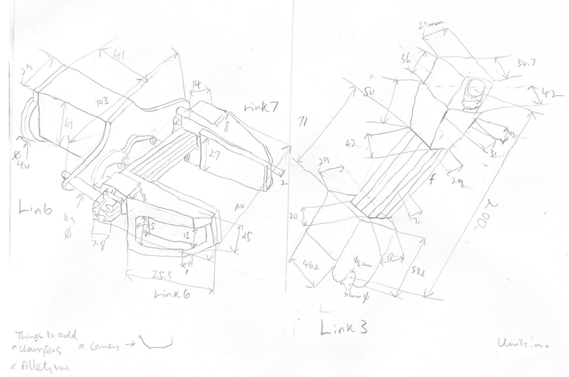
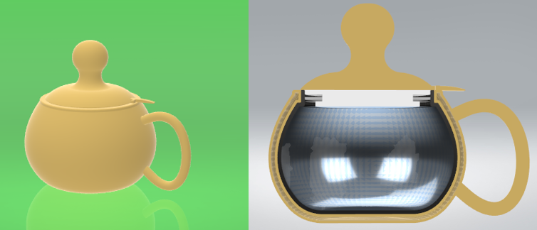
Orieka.O.S.E

//

I love bringing ideas to life through designs and simulations. Design to me is the cross-section of engineering and the arts, and simulation the bridge between the virtual world of design and the real-world.

Design Portfolio

You can rotate, ZOOM In and expande the 3d designs
Spare a few seconds for the designs to load

Rotor

Mechanical ENGINEERING

Course

Basic Engineering Graphics and Computer Aided Design (ENGR 1020)

Overview

A rotor is the moving component of an electromagnetic system that receives electical energy produced from a stator's magnetic field and then transmits mechanical power through the system.

Designed with

SolidWorks

Parts

1. Shaft
2. Core plates
3. Coil windings
4. Metal Contacts
5. Contact holders

DC Motor

ELECTROMECHANICAL Engineering

Course

Basic Engineering Graphics and Computer Aided Design (ENGR 1020)

Overview

A DC motor is an electrical device that converts electrical energy from a DC source to mechanical energy through electromagnetic principles.

Designed with

SolidWorks

Parts

1. Motor housing
2. End contact
3. Magnet
4. Spacer
5. Bushings
6. Rear cover
7. Spur gear

Servo Motor

ELECTROMECHANICAL Engineering

Course

Basic Engineering Graphics and Computer Aided Design (ENGR 1020)

Overview

This servo motor is a rotary actuator that enables the precise control of angular position, velocity and acceleration.

Designed with

SolidWorks

Parts

1. Servo motor housing
2. DC Motor
3. Integrated Circuit
4. Position Potentiometer
5. Multiple gears

Boat

Marine Engineering

Course

Basic Engineering Graphics and Computer Aided Design (ENGR 1020)

Overview

The boat is one of mans' early inventions, and with modern day technology even a simple boat can be designed more effeciently for it's uses.

Designed with

SolidWorks

Interbotix X-Series Robotic Arm

Robotics
Hand Sketches of Link 3 and Link 6

Designed with

Solidworks

Course

Robotics (MENG 4900)

Overview

This designed was made by from hand-made measurements of the Interbotix X-series arm which was translated into a CAD model. This was part of a larger project, developing a Robotics 3D Visualisation and Control Application.

Performed

1. Manual measurements
2. Hand-made sketches
3. SolidWorks design

74LS93 Counter Integrated Circuit (IC)

eLECTRONICS: Digital logics
Unexpanded form
Expanded form

Course

Digital Logics & its Lab (ELEE 2640 & 2650

Overview

Counters such as 74ls93 are sequential circuits which can be designed with JK flip-flops and simulated using the Quartus application. These sequential circuits go through a defined sequence of states upon the application of input impulses.

Designed with

1. System Verilog
2. VHDL
3. Quartus Prime


Performed

1. Recreated the counter using System Verliog and VHDL on the Quartus prime software.
2. A JK flipflop was developed and then used as a module incorporated 4 times to produce the counter and achieve its functionality.
3. Performed a simulation testing the Counter IC design, achieving the same results as specified by the manufacturer truth table.

Field-controlled DC motor

Controls engineering
Motor Schematic
Provided by Professor Richard Hill
Simulink Model Design
ARMATURE CURRENT OUTPUT ia RESPONSE
It approaches 400 A
MOTOR SPEED RESPONSE w(t)
The motor speed approaches 41.3793 radians per second

Course

Control Systems (ENGR 4220)

Developed with

1. Simulink
2. MATLAB

Overview

The field-controlled DC motor has a constant armature voltage (ea) constant, and its speed the speed is controlled by varying the strength of the magnetic field. This is controlled by the field voltage (ef) . The armature circuit has a back emf due to the rotation of the armature. However, the field circuit is stationary; so it has no back emf.

Performed

1. Derived a non-linear differential equation model from the schematic
2. Used Simulink to create a model and simulation
3. Loaded values of constants in the model from a MATLAB script
4. With Matlab some of the simulation results were formatted

Constant Parameters

1. Rf = 240 Ω
2. b = 0.02 Nm/rad/s 3. Lf = 120 H
4. K = 0.0025 Nm/A^2 5. J = 1 kg-m^2
6. La = 0.012 H 7. Ra = 0.6 Ω
8. Kb = 1 V-s/rad

Simplified Automobile Model

Controls engineering
Linear Transfer Function Model
Nonlinear Model
Both approach 31.6 m/s

Course

Control Systems (ENGR 4220)

Designed with

1. Simulink
2. MATLAB

Overview

An automobile can be very simplified by a model that only has the interaction between two forces upon the body of the car., the force that propels the car forward and drag.

Constant Parameters

1. m = 900 kg
2. b = 15 kg/m
3. F¯ = 13, 500 N

4. v¯ = 30 m/s

Performed

1. Designed a a non-linear differential equation model from the differential equation model
2. Produced a linear transfuction model from the linearised version of the differential equation
3. Used Matlab to format the simulation results
4. Loaded values of constants in the model from a MATLAB script

Conclusion
The linearized model had identical results with the non-linear simulink model (the more realistic model) results. This is because the delta F is relatively small. Thus, the linearized model was effective in simulating a simplified automobile because the input to the system being invauleted, a step of 15,000 N, is close to te euilibrum, 13,500 N. Hence, linearized model of complex non-linear models can be effective in reducing the amount of calculation needed and in providing simplified solutions if the input under evalution is close to the equilibrium value.